V-Slot Actuator Kits
About the Kit:
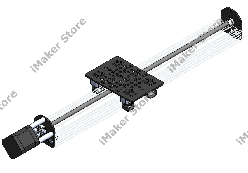
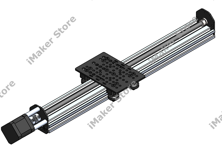
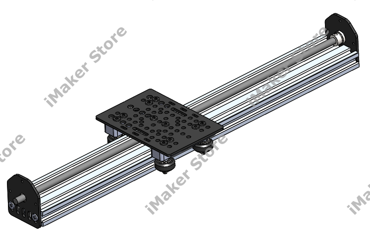
The V-Slot NEMA 17 Actuator Kit is an easy way to get all the pieces needed to build an actuator driven by our ACME lead screw. Sizes available are 500mm, 1000mm, and 1500mm.
The Kit Includes:
| Product No | Product Name | Qty |
| 1 | Universal V-Slot Gantry Plate | 1 |
| 2 | Derlin Solid V Wheel Kit | 4 |
| 3 | M5 Low Profile Screws-40mm | 4 |
| 4 | Spacer Block for V-Slot Gantry Plate | 2 |
| 5 | M5 Low Profile Screws-15mm | 4 |
| 6 | Metric Aluminum Spacers – 6mm | 2 |
| 7 | Mini Eccentric Spacers-8HEX*6mm -Stainless Steel | 2 |
| 8 | Precision Shim T1x5.1x10mm | 4 |
| 9 | Shaft Lock Collar | 2 |
| 10 | Precision Shim T1x8.1x12mm | 2 |
| 11 | 688ZZ Ball Bearing (BE-688ZZ) | 2 |
| 12 | Flexible Coupling-D20L25 8x5mm | 1 |
| 13 | Metric Aluminum Spacers – 40mm | 3 |
| 14 | M3 Cap Head Screws-45mm | 3 |
| 15 | M5 Low Profile Screws-10mm | 4 |
| 16 | Threaded Rod Plate NEMA 17 | 2 |
| 17 | V-Slot 2060-500/1000/1500mm | 1 |
| 18 | ACME/Metric 8mm Lead Screw TR8*8-For V-slot length | 1 |
Tools Required
- Allen keys set
- 8mm spanner/wrench
Follow Step by Step Assembly Instructions:
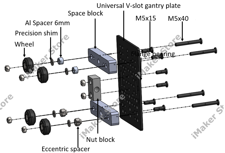
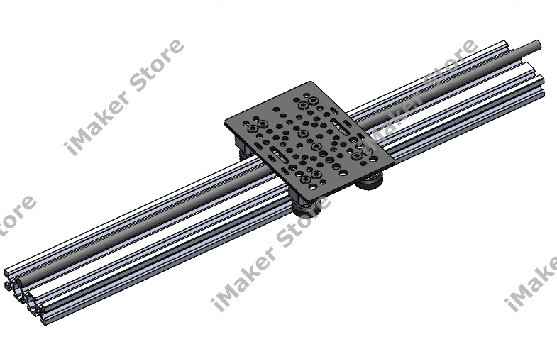
Step1: Gantry cart assembly
Step 2: Attaching gantry cart to V-slot
Note: Make sure that the V-slot rail's ends have M5 threading for attaching the end plates in the later stages of assembly. If you did not order the kit with M5 tapping, you may not find threading at the ends. In such a scenario, it is necessary to manually thread it using M5 taps. Ensure that the threading is at least 15mm deep to simplify the process.
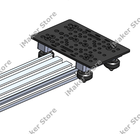
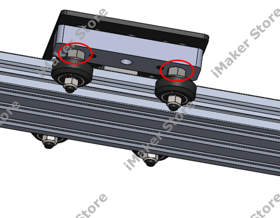
Note: Make sure the gantry cart runs smoothly along the V-slot rail by adjusting the eccentric spacers.
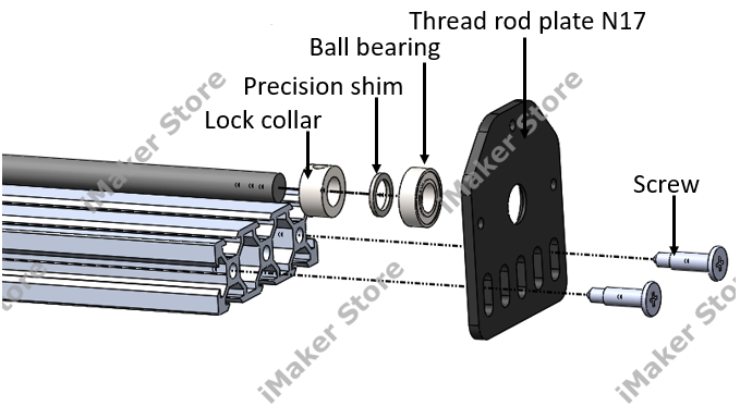
Step 3: Leadscrew assembly
- First, insert leadscrew through the nut block as shown in the image
- Then, insert the collar, shim, and ball bearing at both ends of the leadscrew as shown in the following image.
Step 4: End plate assembly
- Attach the end plates to the V-slot rail using M5x10 screws.
- Check the leadscrew's rotation direction and the gantry cart's movement, and select the appropriate side to attach the motor to.
- In the next step, ensure that the lead screw at the motor end is protruding for fixing the coupling. Take a look at the pictures below.
- Tighten the lock collar screw at both ends of the leadscrew to lock the leadscrew's position.
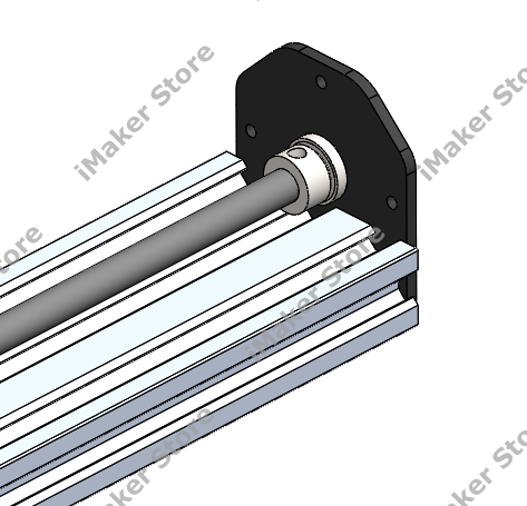
In the below image, it can be seen that the leadscrew is protruding at the end plate for the connection of the coupling and motor.
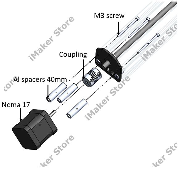
Step 5: Motor assembly
Step 6: Complete the assembly